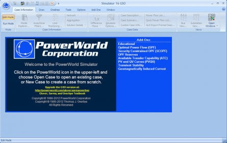

(10) 5.3.2 From your table in 5.3.1, graph the load bus voltage in per unit as a function of load real power in MW. For each step change in load record the following system parameters in a table:

With the series capacitive com- pensation at both ends of the line out of service and the load reactive power fixed at 400 Mvar: 5.3.1 Vary the load real power by increasing it in steps of 200 MW from 0 Mvar to 2600 Mvar. (5) 5.3 Open Power World Simulator case Example 5_10. (10) 5.2.2 From the table you have drawn in 5.2.1, graph the load bus voltage in per unit as a function of load real power in MW. For each step change in load record the following system parameters in a table: The training and testing data for the neural network is obtained by using the Newton-Raphson load flow simulation using Power World Simulator software for different system topologies over a range. With the series capacitive com- pensation at both ends of the line in service and the load reactive power fixed at 400 Mvar: 5.2.1 Vary the load real power by increasing it in steps of 200 MW from 0 Mvar to 2600 Mvar. (5) 5.2 Open PowerWorld Simulator case Example 5-10. (10) 5.1.2 From the table you have drawn in 5.1.1, graph the load bus voltage in kV as a function of load real power in MW. With the series capacitive com- pensation at both ends of the line in service: 5.1.1 Vary the load real power by increasing it in steps of 200 MW until the load bus voltage breaches the low voltage threshold of 0.9 per unit.

Transcribed image text: Question 5 5.1 Open PowerWorld Simulator case Example 5_10.


 0 kommentar(er)
